Example - Adding failure data
Next, we need to add failure data to the architecture model. This needs to be done for each component and, where appropriate, each state.
Fuel Tanks
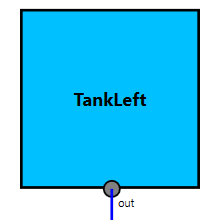
The tanks are identical and have only one failure mode:
| Component Failure | Failure Rate | Repair Rate |
|---|---|---|
| leak | 1e-5 | 5e-4 |
The tanks have a single output port (out) with a single output deviation, omission (O):
| Failure Class | Port | Cause |
|---|---|---|
| Omission | out | this:leak |
Here we specify the output deviation (O@out) to be caused by the “leak” failure mode defined earlier. In this way, we have told Dymodia that an omission of output from this port will be caused by the given failure mode. More complex logic is also possible, as will be seen later.
Since the failure behaviour of the tanks is the same irrespective of which state the system is in, we define the above for the “Default” state, which means it applies in all states.
Left and Right Valves
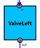
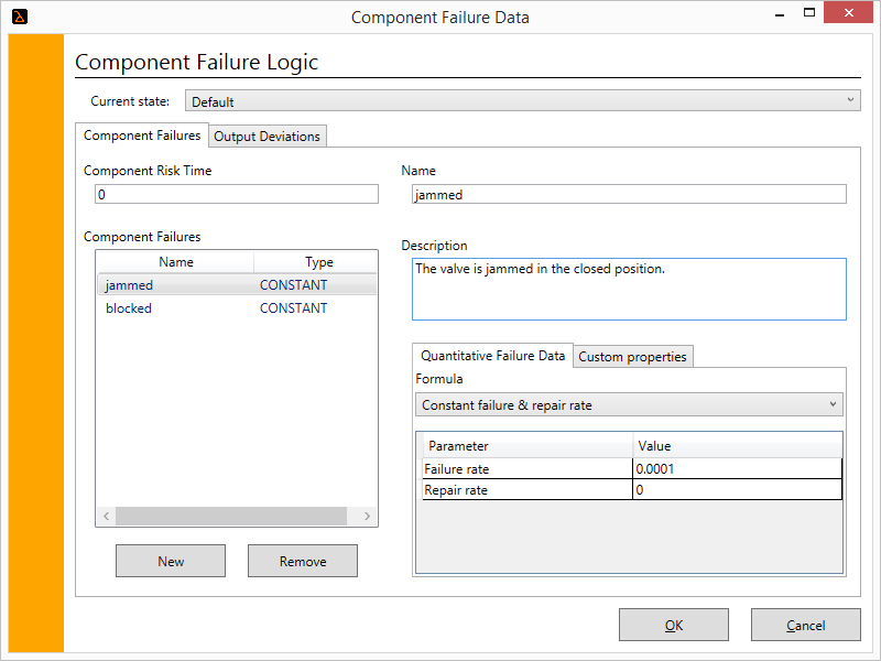
The left and right valves are identical. Each has two possible failure modes: “jammed”, where the valve is jammed in the closed position, and “blocked”, where flow has been obstructed by some kind of blockage.
| Component Failure | Failure Rate | Repair Rate |
|---|---|---|
| jammed | 1e-5 | 5e-4 |
| blocked | 1e-5 | 5e-4 |
We add this information as usual using the Component Failure Data dialogue:
As with the fuel tanks, the valves have a single output port. For now, we can define a single output deviation, omission (O):
| Failure Class | Port | Cause |
|---|---|---|
| Omission | out | this:blocked OR this:jammed OR O@this[in] |
Note how the cause this time is a logical combination of three possibilities: the “jammed” failure mode, the “blocked” failure mode, or an omission of input to the valve (from the fuel tank); any one is sufficient to cause an omission of output.
Again, the failure behaviour here is the same irrespective of which state the system is in, so we only need to define it once, for all states.
Centre valve
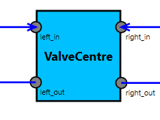
The centre valve is similar to the other valves in its internal failure modes.
| Component Failure | Failure Rate | Repair Rate |
|---|---|---|
| jammed | 1e-5 | 5e-4 |
| blocked | 1e-5 | 5e-4 |
The main difference here is in the output deviations. During normal operation – in the “UseBothTanks” state – this component is dormant; it neither takes input nor provides output, because the valve is closed. Its failure behaviour is only relevant in one of the two degraded modes. As such, we must specify this behaviour directly for each state by selecting it at the top:
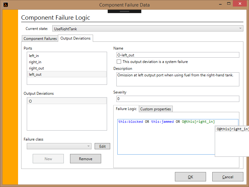
| State | Failure Class | Port | Cause |
|---|---|---|---|
| UseLeftTank | Omission | right_out | this:blocked OR this:jammed OR O@this[left_in] |
| UseRightTank | Omission | left_out | this:blocked OR this:jammed OR O@this[right_in] |
Note how the failure behaviour here depends on the current state; in other words, it is dynamic behaviour. When using the left tank, only output deviations at right_out are possible; when using the right tank, only output deviations at left_out are possible (with appropriate causes in each case).
Left and Right Pumps
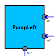
The left and right pumps are identical. Each has only a single generic failure mode:
| Component Failure | Failure Rate | Repair Rate |
|---|---|---|
| failed | 5e-4 | 5e-4 |
However, the output deviations are again dependent on state:
| State | Failure Class | Port | Cause |
|---|---|---|---|
| UseBothTanks | Omission | out | this:failed OR FuelSystem:::PowerCut OR O@this[in1] |
| UseLeftTank | Omission | out | this:failed OR FuelSystem:::PowerCut OR O@this[in1] |
| UseRightTanks | Omission | out | this:failed OR FuelSystem:::PowerCut OR O@this[in2] |
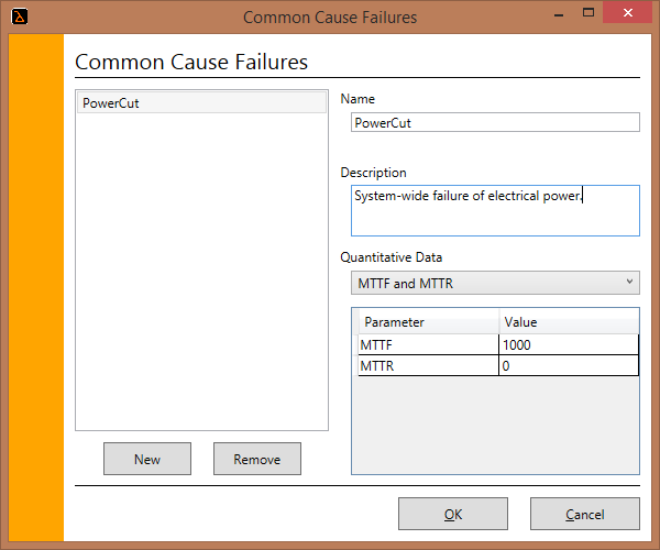
One extra addition here is a common cause failure: “PowerCut”. This is defined at the system architecture level and can then be referenced from any component:
Engines
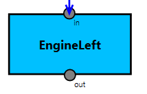
To keep things simple, we do not consider failure of the engines directly; instead we use them only as the “outputs” of the system:
| Failure Class | Port | Cause |
|---|---|---|
| Omission | out | O@this[in] |
In other words, omission of engine power is caused only by an omission of fuel to the engine.