Dymodia
Overview
Dymodia is a software application that allows engineers and safety analysts to model safety-critical systems and perform analyses on those models to help determine the possible impacts of component failures on the rest of the system, whether individually or in combination. Three types of models are possible:
- Hierarchical block diagrams to model static system architecture
- State machines to model dynamic system behaviour
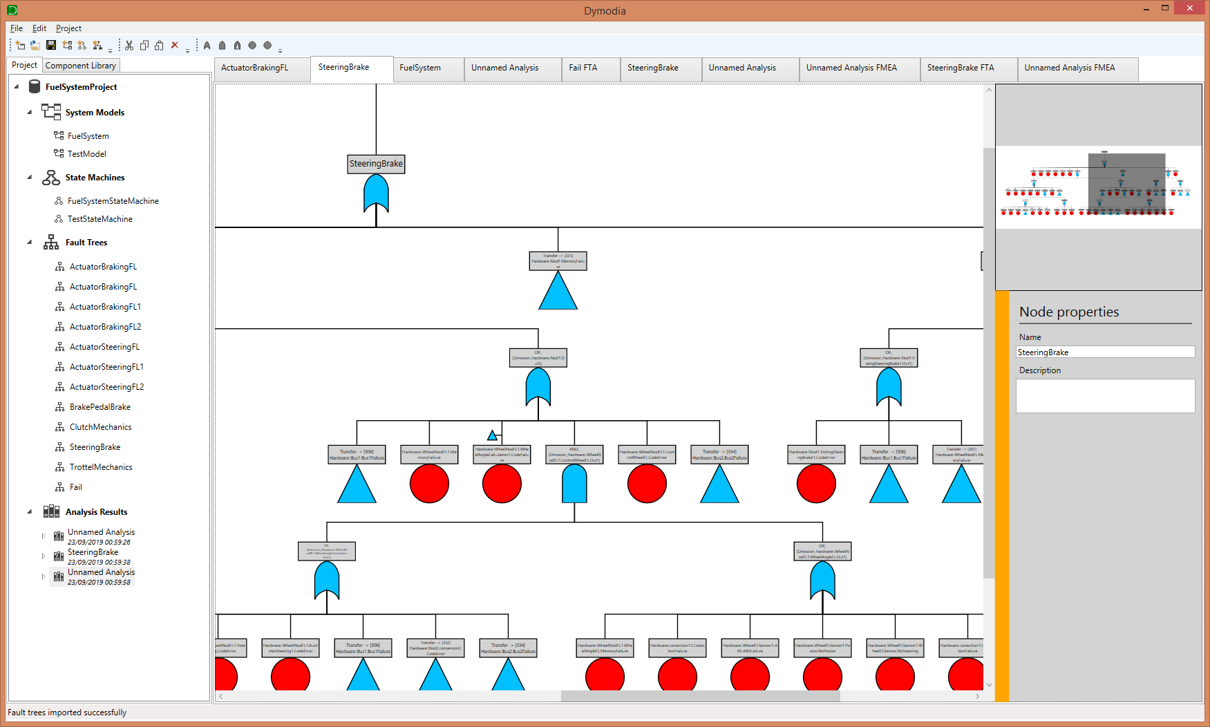
- Static or dynamic fault trees to model additional failure behaviour
These system models can be linked together and annotated with failure data to describe how individual components may fail or propagate failures. Both qualitative and quantitative annotations are possible. From this information, Dymodia can automatically synthesise system-wide models in the form of interconnected fault trees that describe the overall failure behaviour of the system. This process allows a global view of system dependability to be produced from smaller, local views at the component level.
High-performance algorithms can then be used to analyse these global failure models. Dymodia supports Fault Tree Analysis (FTA) as well as Failure Mode & Effects Analysis (FMEA) and crucially also offers support for the analysis of dynamic systems, i.e., systems which can operate in multiple states or in which behaviour changes over time.
Intended primarily as a design-time tool, the results of these analyses can then be used to inform future design decisions, e.g. by altering the design to avoid or mitigate potential faults, and can help to ensure the resulting product complies with international safety standards. Dymodia is unique in combining these different tasks into a single application, directly linking the dependability information to the system models and thereby avoiding the need to manually create or update analysis artefacts in response to design changes. Dymodia should prove useful to engineers in any safety-critical industry.
How it works
The first step is the creation of one or more system models. For smaller systems, this may involve a single system architecture model; for larger, more complex systems, this could include multiple interconnected system architectures – e.g. representing different views of the system, such as separate hardware and software layers – and a state machine to model the dynamic behaviour. More details… The second step is the addition of failure annotations. These typically take one of two forms: standalone fault trees or component-level failure data that describes how a given component may fail. Component failure data includes both internal failure modes as well as deviations of input or output. More details… The third step is the synthesis of global failure models, which describe the propagation of failures throughout the entire system. These can be generated on an individual basis – for example, to show the causes of a particular deviation at a particular port – or encompassing multiple potential system failures, which can be done by synthesising all paths to fail states in a state machine or all causes of a particular global fault tree. More details… Having produced one or more fault trees representing the propagation of failure through the system, the fourth step is analysis. As with synthesis, this can be done on an individual basis – for a particular fault tree – or for a collection of fault trees. The result is an FMEA and one or more FTA results, which include both qualitative results (in the form of minimal cut sets) and quantitative results (in the form of an estimation of unavailability). More details…
Example
To see how Dymodia works in practice, we present an example system as it progresses through each step. The example system is a simplified fuel system with redundant tanks fuelling two engines, such as might be found on a ship or aircraft.