System Modelling
System Modelling
The first step in any project is to model the system itself: the components that comprise the system, the connections between them, and the way the system behaves.
Dymodia supports three types of system model:
- Hierarchical block diagrams to model the static system architecture
- State machines to model the dynamic system behaviour
- Static or dynamic fault trees to model additional failure behaviour
Each of these will be described below.
1. System architecture
System architecture models are block diagrams that represent the topology of the system.
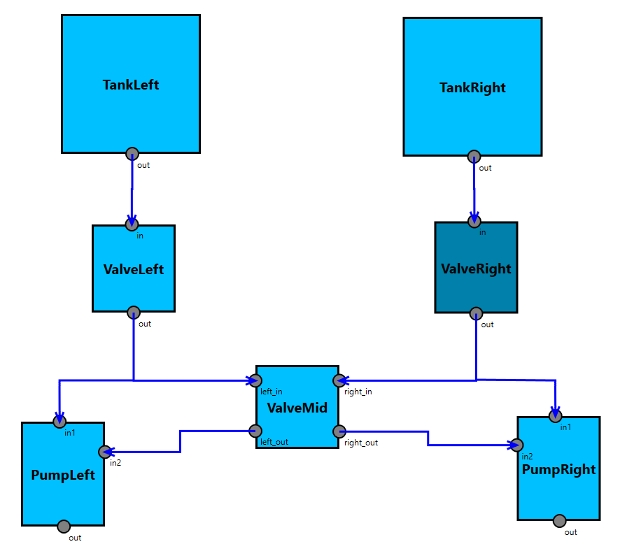
A simple block diagram representing a fuel system
Individual components are joined together via ports (which may be input, output, or both) and connections (either one-way or bi-directional). Components can also contain subsystems, allowing hierarchical models to be defined. Size, colour, and position of components can also be customised.
Users are not limited to a single system architecture diagram. Multiple models can be included to represent different parts, different views, or even different phases of the system being analysed. For example, separate software and hardware architectures could be included, or initial functional models could later be refined into more detailed implementation models.
At present, failure propagations between different models can be defined directly. In future, we plan to allow allocation of architecture models to a component in another model — for example, to represent software running on a hardware component — and allow failure propagation to be determined automatically on the basis of this allocation.
2. State machines
The dynamic behaviour of a system is represented using one or more state machines.
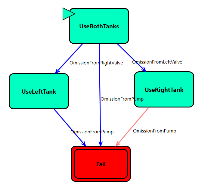
A state machine for the same fuel system
The transitions between states can be triggered by different events in other models, e.g. the top event of a fault tree, a component failure, or a deviation at a component port.
Furthermore, once linked to a state machine describing its dynamic behaviour, different failures and failure behaviour in a system architecture model can be defined per state. In this way, it is possible to model failures that are only relevant in a given state, or changes to the probability or causes of such failures depending on the system’s current state.
3. Fault Trees
Additional failure behaviour can be described directly in the form of a manually-created fault tree.
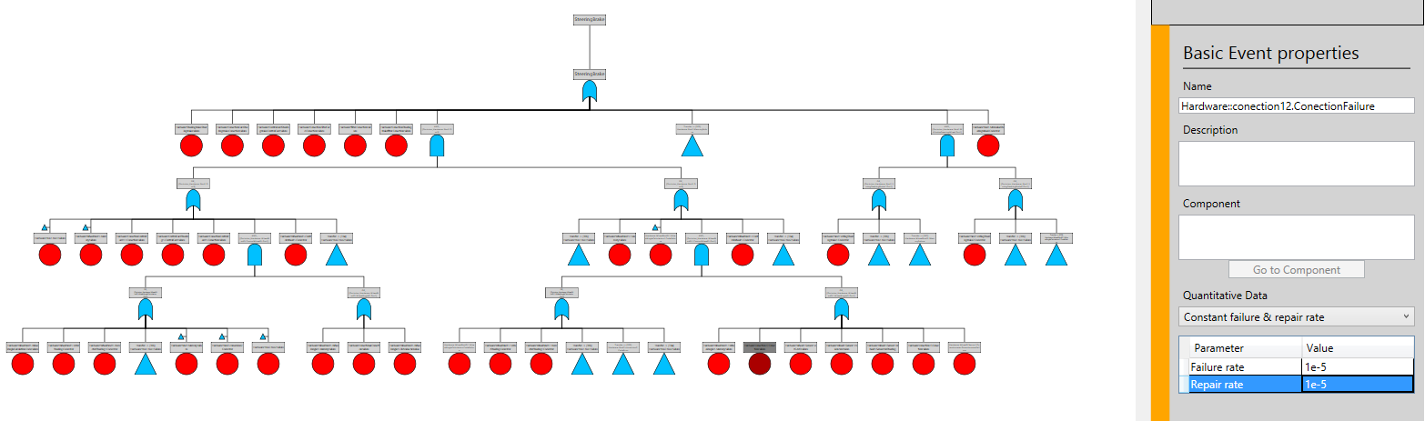
Example fault tree
This can be useful in a number of situations. For example, it is sometimes the case that the failure of a system depends on different combinations of failures at different system outputs, such as in a car braking system: failure of the brakes at a single wheel will have a different outcome to failure of the brakes at both rear, both front, or all four wheels. This type of situation can be modelled directly in a fault tree. Alternatively, it may also be the case that external or environmental causes of failures are required to be modelled. Since these are not part of the system topology, the most natural way to model them is often with a separate fault tree.
Because of the way Dymodia allows causative links between its various model types, it is straightforward to e.g. trigger a fault in a component using a separate fault tree, or have a component output deviation be a leaf node in a high-level fault tree.
Ordinary basic events in the fault tree may include quantitative failure data using different formulae, including:
- Constant failure & repair rate
- Mean Time Before Failure (MTBF) and/or Mean Time To Repair (MTTF)
- Poisson failure rate
- Binomial failure rate
- Dormant failure rate
- Weibull variable failure rate
Dymodia also supports dynamic fault trees using Priority-AND gates, allowing different sequences of events to be modelled, as well as combinations. In future we plan to support non-coherent fault trees with NOT gates as well.